Research on Networked Multimedia
≫ Japanese page

Home
研究内容

Causality Control

Causality represents temporal order relationships.
The delta-causality control is a typical example of causality control. In the control, each MU has a time limit, which is equal to the generation time of the MU plus delta seconds, for preservation of the real-time property. If the MU is received after the time limit, it is discarded since it is considered useless. Otherwise, it is assumed to be output at the time limit.

In the following figure, we show an example of MU output timing under the delta-causality control.

An example of MU output timing under the delta-causality control.

In the above figure, we show the generation timing of MUs at terminals 1 and 2, and the arrival timing and output timing of MUs at the server. In the figure, the value of delta is set to 100 ms.

Terminal 1 generates three MUs at 0, 50, and 100 ms. These MUs are received at the server at 70, 160, and 250 ms, respectively. The last two MUs arrive late. Thus, the two MUs are discarded.
On the other hand, three MUs generated at terminal 2 arrive earlier than their time limits. Therefore, these MUs are output at their time limits.

As a result, we can preserve the causality among the surviving MUs.

Dead-Reckoning

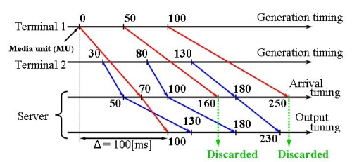
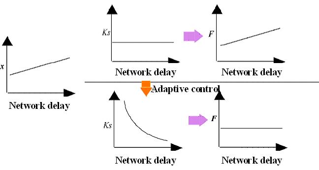
For traffic control of positional information of avatars, objects, and fighters, we can use the function of dead-reckoning.
Especially, since a haptic MU including the positional information of objects is input/output every millisecond (i.e., at a rate of 1 kHz), the function is very important.

In dead-reckoning, the position of each object is predicted. There exist several prediction methods. For simplicity, we show an example in the first-order prediction in the following figure.

An example in the first-order prediction.

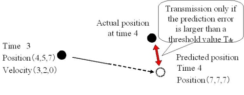
In this figure, we predict the position of a flying ball.
In the first-order prediction, we calculate the predicted position by using the position included in the last received (or transmitted) MU and the velocity calculated with the positional information included in the latest two transmitted (or received) MUs.
That is, (the predicted position) = (the last position) + (the velocity) x (the elapsed time).
Then, we compare the predicted position with the actual position.
If the difference between the predicted position and the actual position (i.e., the prediction error) is larger than a threshold value (Tdr), the information on the actual position is transmitted as an MU. Then, the convergence technique is used. Otherwise, the information is not transmitted at the time.
In the convergence technique, when an MU is received (or transmitted), we correct the position over K ms (K is larger than or equal to 1) in order to correct the position gradually. This is because if we correct the position at a time, the output quality may deteriorate seriously.
We show an example in the convergence in the following figure.

An example in the convergence.

In this figure, the prediction error becomes larger than the threshold Tdr, the actual position is transmitted. Then, the convergence is carried out at several times. At the 8th MU, the ball is output at the predicted position.

Adaptive Control of Reaction Force

Adaptive control of reaction force dynamically changes the elastic modulus, which is used for calculation of the reaction force applied to the user, according to the network delay. The control also controls the force against the object as well as the reaction force. We decrease the elastic modulus as the network delay becomes longer.

The reaction force F is given by (see the following figure)

F = Ks x + Kd v

Ks : Elastic modulus (spring constant) of the object
Kd : Damper modulus of the object
x : Penetration depth of the cursor into the object
v : Relative velocity of the cursor to the object.

Relation between the cursor and the object.

The value of x increases as the network delay becomes longer. According to the equation, the reaction force becomes stronger in this case. Thus, it becomes difficult to manipulation the haptic interface device. For example, buffering haptic media under media synchronization control in order to compensate for network delay jitter is not necessarily desirable. This is the reason why we have proposed the adaptive control of reaction force.

The adaptive control of reaction force tries to keep the reaction force F constant by changing the value of Ks dynamically according to the network delay (see the following figure).

Relation between Ks and network delay.